Overview
This guide takes a licensed auto electrician from an uninstalled Interlock to a commissioned, verified interlock: the two safety rules that decide which wire you touch, the wiring itself, the power-mode choice, field commissioning in the mobile app, and a verification checklist that proves the install behaves.
The unit in the box is marked SIM — the label and the certified model number (PSG-SIM-2285) use the hardware's technical name. That is the Interlock this guide installs.
Before you start
- Role
- Licensed auto electrician, signed in to the mobile app with a Technician licence for the equipment's license group
- An uncommissioned Interlock (D- serial number visible on the label)
- The equipment's wiring diagram
- Basic electrical tools — wire strippers, crimpers, heat shrink, multimeter
- A phone with an internet connection (commissioning is online-only)
- A decision on the wiring mode — see "Choose the wiring mode" below
Warning
Always disconnect the equipment's battery before working on the wiring, and follow your organisation's lockout/tagout procedures.
Safety rule 1: never wire the relay into a run circuit
The Interlock's main relay goes into a starter-solenoid circuit or an operator-presence circuit. Never a circuit that carries current while the engine runs.
This is a hard requirement, not a preference. The Interlock locks the moment it decides to lock — there is no grace period and no wait for the operator to shut down. That is safe only because of this rule:
- Starter-wired, the circuit carries no current while the engine runs. Opening it cannot stop the machine; it only prevents the next start.
- Presence-wired, opening the circuit looks exactly like the operator standing up — a condition the machine's own safety systems already handle.
An install that breaks this rule turns every lock decision into an engine cut. There is no software setting that makes such an install safe.
Safety rule 2: use the correct relay terminals
The interrupted circuit goes through J5 (SW1_COM) and J6 (SW1_NC).
The main relay is energised when the Interlock is locked, and energising it closes COM-NO. So the can-start position is the de-energised one, COM-NC — and that is the pair the interlock belongs on.
Danger
Wiring J5 + J4 (SW1_NO) inverts the safety behaviour. Equipment would not start until the
firmware booted, and would never start at all from an Interlock that is dead, unpowered, or
sitting in the bootloader. The board cannot tell the two apart — both contacts come out to
identical terminals with identical snubbers — so nothing downstream of you catches this mistake.
Check the terminal numbers before you crimp.
Choose the wiring mode
The Interlock supports two wiring modes. Pick the one that suits the machine, then record it as the device's Mode during commissioning — the device itself neither knows nor detects how it was wired.
| Mode | Where the relay goes | What happens while locked |
|---|---|---|
| Starter (engine-start inhibitor) | Inline with the starter-motor circuit | The machine will not start. A running engine is unaffected. |
| Safety (operator-presence inhibitor) | Inline with the seat switch or equivalent presence circuit | The machine starts and stops normally, but cannot be fully operated — it reads the seat as vacated. |
What "cannot be fully operated" means — hydraulics lockout, drive inhibit — is the machine's own behaviour. The Interlock only interrupts the signal path.
Note
The sense input goes to the ignition-switched line on every install, Safety included (step 4). A Safety-wired machine fitted before October 2026 may still have its sense input on the operator-presence circuit, and is rewired at its next visit. Until then, anything labelled "ignition" in the console or the app is reporting presence on that device, and the engine-hours counter measures occupancy rather than engine time.
Choose the power mode
The Interlock can be fed two ways, and the choice changes how the sense line is wired:
- Permanent power (the default) — the Interlock is fed from an unswitched supply and stays powered with the key off. The sense input must be wired in this mode, to the ignition-switched line on Starter and Safety installs alike. An unwired sense input reads as permanently inactive, and the operator timeout would fire mid-shift on every job.
- Ignition power — the Interlock is fed from the ignition-switched circuit itself and powers down with the key. The sense input stays unwired (power itself is the signal). A machine wired this way boots locked on every key-on and needs a fresh unlock each time: a Confirm in the app while the last pre-start is still valid, otherwise a new pre-start. The operator timeout never applies, because the Interlock powers down with the key.
The power mode is recorded at commissioning and is kept even if the unit later changes hands, because it describes how the machine is physically wired.
Installation steps
- 1
Identify the circuit to interrupt. For Starter mode, locate the wire carrying the start signal from the key switch to the starter solenoid or engine controller. For Safety mode, locate the operator-presence circuit — typically the seat switch. Consult the equipment's wiring diagram, and confirm the circuit is dead while the engine runs before going further.
- 2
Mount the Interlock. Secure the Interlock in a protected location inside the cabin or engine bay, shielded from water, excessive heat, and direct vibration, with the BLE antenna path toward the operator's position as clear as practical. Mount it out of casual sight — the Interlock is hidden for tamper resistance, unlike the GoTag, which is meant to be found and scanned.
- 3
Wire the power supply. For permanent power, connect the Interlock's power input to an unswitched 12 V or 24 V source (anywhere in the 6–36 V DC range) and a clean chassis ground. For ignition power, feed it from the ignition-switched circuit instead.
- 4
Wire the sense line (permanent power only). Connect the sense input to the ignition-switched line, on Starter and Safety installs alike, so the Interlock knows when the key is on.
- 5
Wire the relay through J5 and J6. Cut the circuit you identified in step 1 and connect each end to J5 (
SW1_COM) and J6 (SW1_NC). Do not use J4. - 6
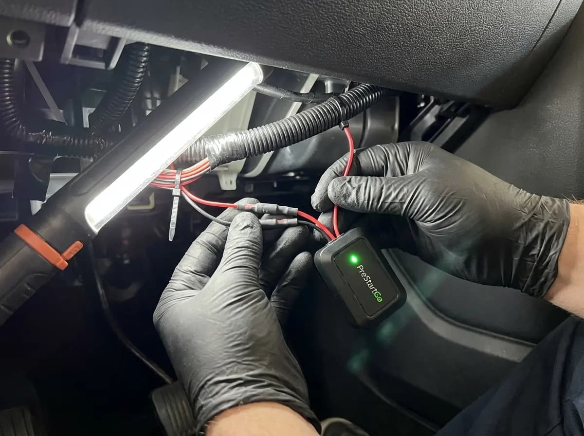
Reconnect the battery and power the machine without starting the engine. A factory-fresh, uncommissioned unit shows a flashing green LED — that is the "not yet registered to any organisation" state, and it is what you want to see at this point.
Commission the device
Commissioning binds the Interlock to the organisation and the machine, in one online action:
- 1
Open the equipment in the mobile app (or scan its GoTag) and start the commissioning flow, entering the Interlock's
D-serial from the label. You need a Technician licence for the equipment's license group, and the machine must not already have an active interlock. - 2
Stay at the machine for the confirm press. The platform issues a signed registration that your phone relays to the device over BLE. The Interlock's LED turns flashing purple and it waits up to 30 seconds for a press of its mode button — the physical proof that someone is standing at this exact unit. Miss the window and nothing is saved; simply start again.
- 3
Set the machine's settings. During commissioning you record the wiring Mode (Starter or Safety) and the device's behaviour settings. Machine settings are set here, at the machine, by the technician — the office console displays them read-only.
Once confirmed, the device is registered, billing for its device subscription starts, and the LED settles on solid red — locked, awaiting the machine's first pre-start.
Post-installation verification
Run through every line before handing the machine back:
- Uncommissioned power-up showed flashing green; after commissioning the LED is solid red (locked)
- The interlock is on J5 + J6, and a de-energised Interlock leaves the circuit closed — pull the Interlock's fuse and confirm the machine can still start
- Starter-wired: the engine starts only after a passing inspection unlocks the Interlock (solid green)
- Safety-wired: the machine starts either way, but cannot be fully operated while locked
- Complete a pre-start in the app and confirm the relay closes; then let the validity window expire and confirm the relay opens immediately, with no grace period
- The recorded Mode matches how the machine is actually wired
- The sense input tracks key position — watch the state change in the app while cycling the key
Troubleshooting
| Symptom | Likely cause | What to do |
|---|---|---|
| LED dark after reconnecting the battery | No power reaching the unit | Check supply, ground and fuse; confirm voltage is within 6–36 V DC |
| Flashing green never becomes flashing purple | The registration never reached the device | Stay within BLE range, confirm the phone is online, and restart the commissioning flow |
| Flashing purple returned to flashing green | Confirm window timed out (30 s) with no button press | Nothing was saved — run commissioning again and press the mode button promptly |
| Amber flashing after commissioning | The device's self-test found a fault | The unit still allows starting (Fail-START); reconnect with the app to trigger recovery, and contact support if it persists |
| Machine cranks while "locked" (Starter mode) | Relay wired through J4 instead of J6 | Rewire through J5 + J6 — see safety rule 2 |
| Operator timeout fires mid-shift | Sense input unwired on a permanent-power install | Wire the sense line per step 4 |